




Why buy from us?
Lorem Ipsum is simply dummy text of the printing and typesetting industry.
Ask a Question About This Product
- Stock: In Stock
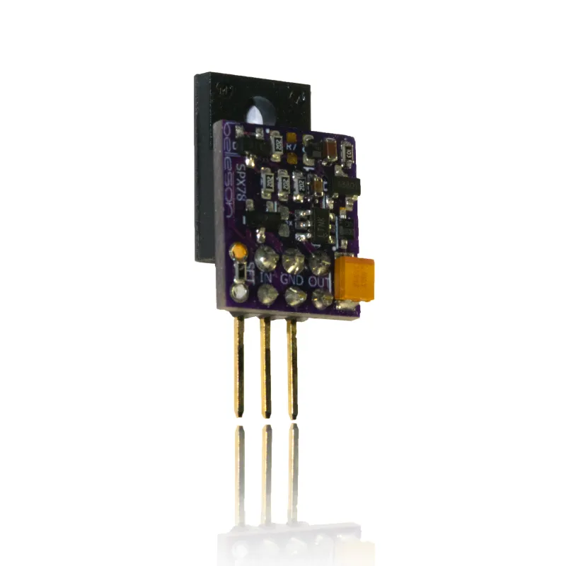
- Model: SPX78
- Weight: 0.10g
- Dimensions: 0.10in x 0.50in x 1.03in
- SKU: SPX78
- Location: GREER
Noise Comparison
How does SPX noise compare with other voltage regulators? See the noise spectra below and judge for yourself. All devices were tested with the same input supply, gain of 1000 measurement amplifier, and spectrum analyzer. All were measured as the AC component of 12VDC output, with no load. The vertical scale of all spectra was lowered by 60dB to adjust for the 1000x gain.
Baseline Test System Noise

This is the noise level of the test setup with input grounded. Spectrum is captured from a Handyscope HS3 from Tiepie Engineering. How low can you go? The small spike is power line noise leaking through at 60Hz, -155dBVpk. The trace gets thicker at higher frequencies because of the logarithmic horizontal scaling.
SPX78
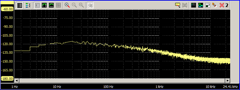
Belleson's SPX has very low noise, about 8µVrms across the audio band.
Sparkos Labs
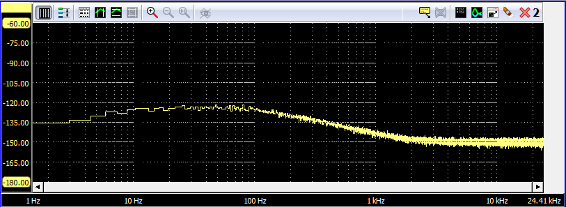
Sparkos Labs SS7812 has very low noise, about 6µVrms in our test setup.
LT3045
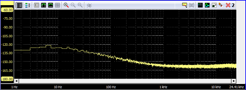
LT3045 measures just over 2µVrms.
Dexa/NewClassD LC7812 UWB Mk2

Surprisingly, the new Dexa LC7812 UWB Mk2 measures about 110µVrms in our test setup.
TPS7A4700
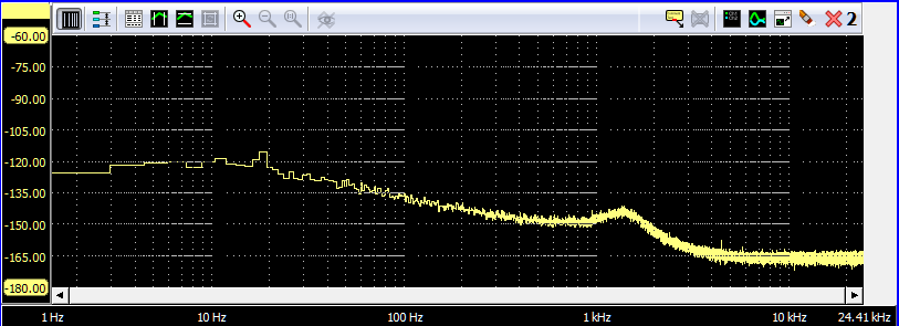
Very low noise, measures about 3.5µVrms in our fixture. Its other characteristics such as output impedance and dynamic response are not very good.
SPX dynamic step response compared to newer regulators
First, why is dynamic step response important?
Dynamic step response is a measure of how a regulator output is affected by a demand for a lot of current in a short time. Ideally, output voltage does not change at all, no matter how much current is demanded, nor how fast. Unlike instant coffee, reality and the laws of physics prevent "instant" response from a voltage regulator. We can test this response using a switch to increase current demand for a short time and watch the output voltage with a fast oscilloscope to see how it responds. These comparisons are exactly that, using a 150MHz Hitachi V-1150 high speed analog oscilloscope.
Measurements are taken in the same test socket, with the same input stimulus and output sense for all devices. Measurements may differ from those you see in manufacturers' data sheets because of different setup, e.g. input or output capacitance, placement of sense device, wire lengths, etc.
Maximum output current is different for the various devices. To make it a fair test, the current step is 250mA, which is ½ the maximum for the lowest output devices. All regulators also have 100µF output capacitance and a 500Ω resistor for a 24mA DC load, which helps the trailing edge response settling time.
The LT3045 and TPS7A4700 are both surface mount monolithic devices that require a PCB to allow them to be plugged into a TO-220 style test socket. The tested devices were, when purchased, mounted on a PCB with MLCC capacitors already connected. Replacing the MLCCs with tantalum on the TPS7A4700 PCB significantly improved performance, and the measurements you see here are with 10µF tantalum.
The SPX is so fast that a ferrite bead had to be added to the pull-down transistor to prevent high frequency ringing in the response.
See the oscillograms below and judge for yourself. Top trace is the output current measured with a Tektronix current probe. The more important bottom trace is regulator output voltage, which should be perfectly flat for an ideal regulator. See notes below for more information on the tests.
Belleson SPX78 leading edge
 Belleson's new SPX settles in less than 1µsec for both leading and trailing edge of a 250mA current step.
LT3045 leading edge

Sparkos leading edge

TPS7A4700 leading edge

Dexa 2 leading edge

Belleson SPX78 trailing edge
 Belleson's new SPX settles in less than 1µsec for both leading and trailing edge of a 250mA current step.
LT3045 trailing edge

Sparkos trailing edge

TPS7A4700 trailing edge

Dexa 2 trailing edge

Ripple Rejection
Why is ripple rejection important?
Ripple rejection is a measure of how well a regulator blocks anything and everything "bad" on the input voltage from getting to its output. This is a hard requirement to meet because bad stuff can be any of
- low frequency power line voltage fluctuations
- higher frequency power line noise from other connections on the same circuit (e.g. LED bulbs or AC motors)
- frequency digital switching noise (from SMPS)
- rectifier diode off/on transient glitches
- EMI signals coupled into the circuit
- various others
Thus ripple rejection must ideally block all non-DC signals across an infinite bandwidth. While this is not possible, it is important to know how well a regulator rejects input "noise or whatever" across a broad frequency band. For audio specifically, we measured it out to 200kHz with a 150MHz bandwidth oscilloscope and a swept sine wave imposed on the regulator's input voltage.
Ripple rejection (PSRR) has been the most difficult to make of all our data sheet measurements. After making a (fourth) measurement fixture because of high frequency feed-through, we have a new set of measurements for a new generation of regulators. To read the full story, see this article on the AudioxPress web site.
Here is what we measured, where higher numbers represent better rejection, thus less ripple that gets to the regulator output:

Keep in mind that 120dBV represents 1µV and 100dBV is 10µV of ripple at the output.
The test is done as described below using ±0.5V sine wave on top of 15Vdc. Notice that SPX reduces ripple by 120dBV at 80KHz, unrivaled in the world as far as we know!
Our customers' comments that their systems sound better with Superpower are backed up by measurements—order one to hear for yourself, it really is this good.
To see all the details with spectra, see this page with comparison graphs.
The source fixture uses a DC+AC driver using an op amp servo feeding a low impedance MOSFET to deliver a good sine wave on top of a DC voltage.

We did direct comparison measurements by setting up the fixture, setting Vin and frequency and plugging in each of the regulators in turn. Testing was done with no load. A 16 bit 195K sample/second autoranging A/D was used for the FFT measurements. Measurements were made from 55Hz to 80kHz. Of course we use our regulators to power the circuitry to test our regulators!
Output Impedance
Why is output impedance (zout) important?
A power supply is a source of current from a fixed voltage. Any impedance at the power supply output (zout) is in series with the load impedance being driven by the supply. The supply impedance and the load impedance form a voltage divider, so as the load requests current from the supply, the voltage at the load will change by the amount zout * iload.
Thus lower zout delivers fundamentally better voltage regulation. Watch the first three minutes of a video from Texas Instruments to learn more [choose Low distortion design (4) and topic External sources].
SPX Output Impedance vs. Frequency
What is Superpower's output impedance? Amazing! Here is a graph of Zout vs. frequency, showing a 50mΩ maximum impedance while delivering 10mA from 20Hz to 200KHz. This is measured on a typical production SPX78 with 12V out.

What are we showing you?
In this test, a 10mA AC current is pulled from the regulator output (top trace, at 10mA/div), as frequency of the current is swept from 20Hz to 200kHz. The AC voltage appearing at the output of the regulator (bottom trace at 50mΩ/div by using a gain of 1000 amplifier) represents the output impedance, where zout=vac/iac. Voltage is graphed on an oscilloscope where you can see frequency change across the horizontal axis at 20kHz per division.
SPX zout stays low across ten times the audio band. We dare you to find or build a better regulator! Take a look at our Zout comparison page to see how SPX compares to other available voltage regulators.
Superpower Output Impedance compared to other regulators
Belleson's newest SPX regulator was multiple years in development, and designed to have the lowest possible output impedance while keeping the circuit fast and stable.
How does Superpower compare with other voltage regulators? See these oscillograms and judge for yourself. Test notes are at the bottom of the page.
Why is low zout desirable?
Output impedance, or zout, is a small signal measurement of a regulator's ability to deliver current while vout remains constant. Any deviation from constant represents a voltage drop across the output impedance due to the AC excitation current from the output.
In this test, a 10mA AC current is pulled from the regulator, as frequency of the current is swept from 20Hz to 200kHz. The AC voltage appearing at the output of the regulator represents its output impedance, where zout=vac/iac.
If you look at a power supply as a source of current from a fixed voltage, any impedance at the power supply output is in series with the load impedance being driven by the supply. That load is, for audio, typically one or many amplification devices. The supply impedance and the load impedance form a voltage divider, so as the load requests current from the supply, the voltage at the load will change by the amount zout * iload.
Thus lower supply zout delivers fundamentally better supply voltage regulation. To learn more, watch the video from TI on this page. Find Topic "Low Distortion Design" and watch the first 3 minutes of "External sources" video.
SPX78
Belleson's SPX78 has very low zout at audio frequencies and increases gradually to 50mΩ at 200kHz.
Sparkos
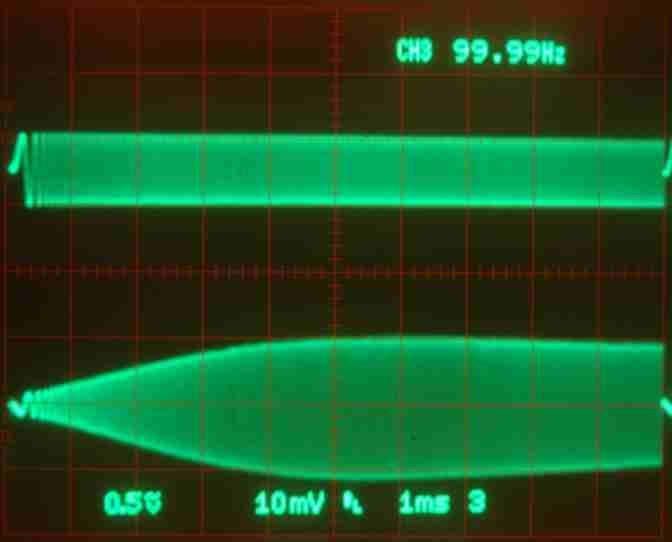 zout for the Sparkos SS7812 grows to 110mΩ at 110kHz then decreases slightly toward 200kHz.
LM7812
 The LM7812 with high impedance around 10kHz and its noisy. zout is set mostly by the output capacitor.
LT3045
 The LT3045 from Analog Devices has a Zout that increases in a slight bow up to 60mΩ at 200kHz.
TPS7A4700
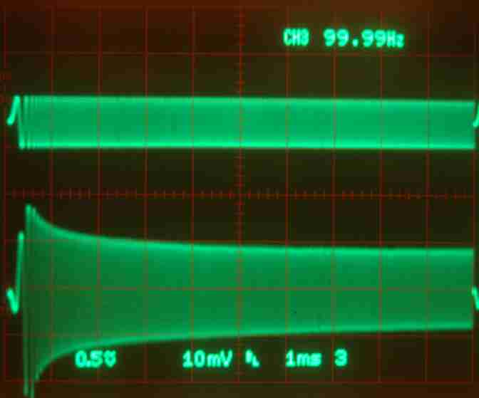 The TPS7A4700 from TI has a bloom in the audio band, where zout is about 200mΩ at 10kHz.
Dexa/NewClassD LC7812 UWB Mk2
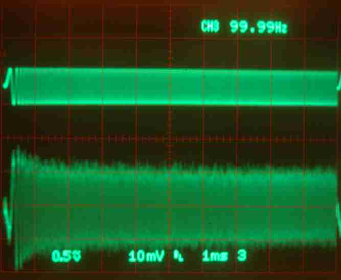 Relatively high zout with a peak in the audio band up around 180mΩ , and visible noise.
Notes
Measurements are taken in the same test socket, with the same input stimulus and output sense for all devices. Measurements may differ from those you see in manufacturers' data sheets because of different setup, e.g. input or output capacitance, placement of sense device, wire lengths, etc.
Voltage is amplified by 500 and graphed on an oscilloscope. You can see frequency change across the horizontal axis at 20kHz per division.
The top trace is output current as measured with a Tektronix current probe amplifier set to 10mA per division. For some regulators the change in vout is too low to be useful so we fed it through our noise amplifier to give it a gain of 1000. Thus the bottom trace is 1000 x regulator Vout.
The LT3045 and TPS7A4700 are both surface mount monolithic devices that require a PCB to allow them to be plugged into a TO-220 style test socket. The tested devices were, when purchased, mounted on a PCB with MLCC capacitors already connected. Replacing the MLCCs with tantalum on the TPS7A4700 PCB significantly improved performance, and the measurements you see here are with 10µF tantalum.
It's possible that zout graphs of the lowest measured parts have some error due to feed–through in the test fixture. Thus zout could be lower than we measured.
How to set output voltage of variable SPX?
SPX17, SPX78 and SPX79 are available with variable output by adding a resistor here:
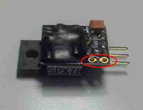
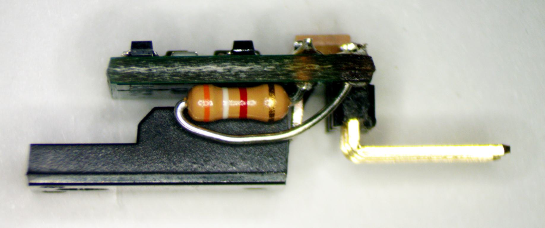
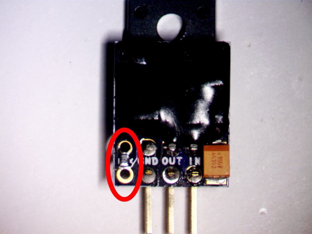
When shipped, variable SPX has Vout=30V, so add a resistor to set the correct voltage before you connect it and power it on!
The only difference between variable and fixed Vout is if we add the extra resistor or if you add it. We add a thin film 0603 SMD, you can add same or a ⅛W resistor of your technology choice. The additional Rset resistor is in parallel with a 10k resistor so Vout change is not linear with Rset change. You can also add a 4th pin and put a fixed resistor or potentiometer on the main PCB. See the chart below for values.
Calculate Rset in kΩ as
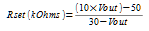
Typical values are
| Vout | Rset in Ω | Nearest 1% value (Ohms) |
Nominal Vout |
| 5 | 0 | 0 | 5 |
| 6.3 | 548.52 | 549 | 6.3 |
| 7 | 869.57 | 866 | 6.99 |
| 8 | 1363.64 | 1370 | 8.01 |
| 9 | 1904.76 | 1910 | 9.01 |
| 10 | 2500 | 2490 | 9.98 |
| 12 | 3888.89 | 3900 | 12.01 |
| 12.6 | 4367.82 | 4320 | 12.54 |
| 15 | 6666.67 | 6650 | 14.98 |
| 16 | 7857.14 | 7870 | 16.01 |
| 18 | 10833.33 | 10700 | 17.92 |
| 20 | 15000 | 15000 | 20 |
| 24 | 31666.67 | 31600 | 23.99 |
| 30 | none | none | 30 |
You can use a potentiometer to set Vout. A 50k trimmer will adjust from 25.8V to 5V, a 100k trimmer will adjust from 27.7V to 5V. The trimmer is in parallel with a 10k resistor so Vout change is not linear with resistance change.
How does SPX work better than other voltage regulators?
A unique circuit, granted US patent 8294440 in 2012, uses a JFET as a voltage level shifter, allowing a precision current source and feedback loop to be powered from the quiet, clean, low noise regulator output. The precision current is used to offset the floating regulator, allowing it to work at any output voltage. For more information, read this white paper, or the patent.

SPX78 and SPX79 mounted to heat sinks on a PCB
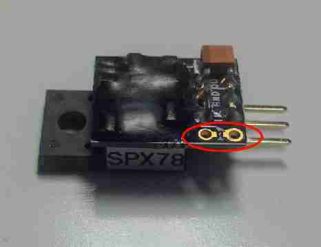
SPX with variable output is shipped with 30V out. Add a ¼W resistor between the two holes near the Rset pin to change to any Vout down to 5V. Or you can order with a standard fixed output voltage as a plug-in LM78xx replacement!
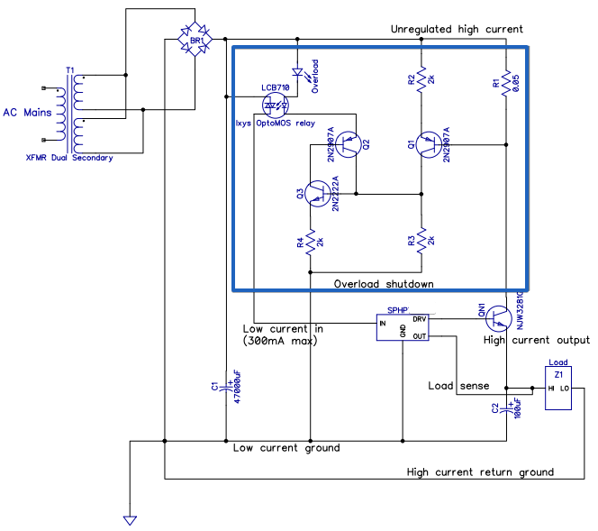
Belleson's SPHP Superpower can deliver up to 10A at 100V. This is enough for most power amplifiers and to replace noisy and slow switched mode power supplies in computer based music servers. High current circuit design requires careful thought about power dissipation, where current flows and other important topics. We'll discuss this diagram of a basic power supply using SPHP:  . To start, let's define some terms:
- VIN
- Input voltage to regulator
- VOUT
- Voltage regulator output
- VDO
- Regulator drop-out voltage: minimum (VIN-VOUT) to keep regulation
- IL
- Load current from regulator output to its load and back to power source (typically a transformer+rectifier+filter)
- PL
- Load dissipation: VOUT / IL
- PR
- Regulator dissipation: (VIN - VOUT) / IL
- LDO
- Low Drop Out
- VRIP
- Input Ripple, the AC change at VIN
Power Dissipation—Regulator vs. Load
SPHP can provide up to 1000W to a load while the regulator can dissipate 200W. Total load dissipation is thus 1200W. You must choose a power transformer with high enough VA to supply the total power.
Any power used by the regulator is not delivered to the load and is considered wasted. Given regulator power dissipation = drop-out voltage times load current, it's easy to see why low drop-out voltage is important, and why LDO is a standard acronym in regulator data sheets. The closer VIN is to VOUT, the less power is wasted.
Drop–Out Voltage and Supply Efficiency
SPHP drop-out, as for most linear regulators, increases with load current to a maximum of 3V at 10A. Thus it is theoretically possible to make a 1000 Watt power supply with 30W of wasted power, giving an efficiency of 97%. Practically speaking, however, an efficiency of 80% is considered great for a high power linear supply. Why is this?
Looking at the above schematic, AC current is rectified by bridge rectifier BR1 and filtered (smoothed) by capacitor C1. After mains power is applied, C1 charges to its peak DC value and will remain charged until current is requested by the load. Realize that C1 only charges when the peak voltage from BR1 goes above C1 voltage so for much of the AC cycle, C1 can supply current but not receive it.
Input Ripple Voltage and Regulation
While C1 is supplying current and bridge voltage is below C1 voltage, C1 discharges. There is a long time (relative to a power line cycle) when C1 discharges and a short time when it recharges. This is what makes the familiar saw tooth voltage ripple at the input to the regulator. 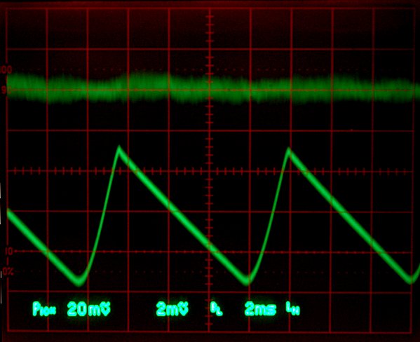
As you know, i=Cdv/dt and higher load current discharges C1 more quickly. If C1 discharges enough during an AC power line cycle to go below (VOUT+VDO), the regulator stops regulating!
Regulator Input Capacitance and Drop Out Voltage
Look again at i=Cdv/dt. Rearranging terms gives dv=idt/C to show that ripple is reduced by increasing C. Now rearrange again and substitute frequency f=1/dt to get an equation for C1 given load current and maximum desired ripple: C=i/(2fdv). The factor of 2 is because BR1 is a full wave rectifier and C charges twice per cycle. A half wave rectifier does not have this factor.
For 10A load and 1V maximum ripple at a 50Hz power line cycle (worst case, also makes the math prettier), and 1V maximum ripple target, the required C1=10/100, or 100000µF. The 47000µF value assigned to C1 in the above schematic will allow about 2.5V maximum ripple voltage.
Given that the minimum ripple voltage must stay above VOUT+VDO, the voltage at BR1 must go above VOUT+VDO+VRIP to keep C1 charged enough to allow the regulator to function correctly. For a 12V regulator, BR1 voltage must stay above 12+3+2.5=17.5V using C1=47000µF. This explains why a supply efficiency of 97% is unrealistic. For this 12V regulator, efficiency is 100 x 12 / 17.5 = 69%. Even with C1=100000µF, efficiency goes to 75% which wastes 1/4 of the input power. Ripple depends only on load current, so given the same load and VDO, a higher VOUT supply will be more efficient than a lower VOUT supply.
Here is a really good tutorial on building a 10A power supply
General Conclusions
- Power dissipation by the regulator is linear as (Vin-Vout)*(load current)
- (Vin - Vout) is RMS voltage
- If Vin is fed from a rectifier+filter cap, Vin is not DC but has ripple
- Ripple has a linear dependence on load current as
dv=i/(2fC)
where dv = ripple amplitude, i=RMS load current, f = power line frequency and C=filter capacitance - Minimum peak of ripple must not go below (Vout + Vdropout), otherwise regulator stops regulating
From this we conclude:
- Larger filter capacitance = lower ripple
- Lower ripple allows lower Vin
- Lower Vin allows lower regulator power dissipation
More Overhead
For the chosen 12V supply, the transformer must keep VIN above 17.5V to maintain regulation. With high current demand, transformer secondary voltage tends to sag (decrease). The peak unloaded voltage of the transformer must be increased to account for sag, and also to account for the worst case low primary voltage. Ultimately this transformer must have a 20V to 24V peak output voltage due to these multiple system constraints.
High Current and Physical Design
Now that we've decided on a set of components: SPHP regulator, power transformer, bridge rectifier, large filter capacitor, how do we connect them? Two important factors in wiring an accurate high current power supply are wiring resistance and stability. At 10A, 10mΩ equates to a 0.1V drop. As current changes through an impedance, it will modulate the voltage at the load, so even with a perfect voltage source, a changing high current load can modulate the voltage at the load due to wiring resistance.
SPHP is designed with a small PCB controller and a separate high current output transistor (QN1 in the schematic). This allows the control loop to be independently placed and wired with a maximum current of about 250mA, and QN1 can be separately heat sink mounted with large currents flowing separately through it.
The diagram below shows physical wiring of the above schematic with matching wire colors. Notice the red path of high current from the raw supply to the power transistor to the load and back to the raw supply. Make this path short, from heavy gauge copper trace or wire. The black and green DRV current paths can be smaller, they will have approximately 250mA at full 10A regulator current. The other paths are very low current.
 .
.
Two external protection diodes allow stored charge from large capacitance to by-pass the regulator at power-down if input voltage falls faster than output voltage or if VOUT gets pulled below ground by some load related condition (e.g. an inductive load). Even though SPHP has internal protection diodes, larger external ones such as 1N4004 are recommended.
SPHP has no built-in stabilizing capacitor, so an external one must be connected from VOUT to ground as shown here. This should be 100µF or more and have a voltage rating higher than VOUT. Also notice the diagram is not to scale—the capacitor will be bigger than the Superpower :-).
The power transistor supplied with SPHP is NJW3281G, a 250V, 15A, 200W device.
Preventing Damage
With 10A+ available, it's easy to damage a regulator with even the briefest of short circuit to ground. The fast shutdown circuit shown below can prevent this:
 .
.
It's a latching protection circuit that shuts off the internal control loop and prevents any output current from the regulator. To reset, VIN must be powered down and up again.
Good Luck!
Hopefully this is sufficient information to build the power supply of your dreams! Contact us with any further questions and we'll help.