Why buy from us?
Lorem Ipsum is simply dummy text of the printing and typesetting industry.
Ask a Question About This Product
- Stock: In Stock
- Model: SPX17
- Weight: 0.10g
- Dimensions: 0.10in x 0.50in x 1.03in
Available Options
Low Noise, Fast Dynamic Response, Superb Ripple Rejection, 3A Current
"The best solution is a well-designed power supply in the audio gear itself." Ed Simon's conclusion of a 5 part article on cleaning up AC power lines in AudioXpress, Aug - Dec 2008.
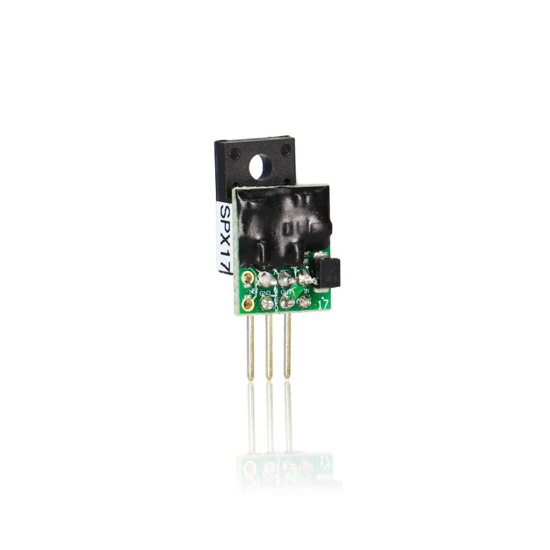
Now you can have the best solution! Today's 24 bit and higher circuits demand the best voltage regulation, and the Belleson Superpower gives it to you. The patented design fully isolates almost all circuitry from the input voltage, providing the best line regulation possible. The innovative design delivers current faster and cleaner than ever before available, with the lowest possible output impedance!
Bootstrap powered by its own clean, quiet output voltage, the Superpower has amazing load regulation, low noise and dynamic performance, delivering 3 Amps of output current.
You may have heard of a "super regulator" designed by noted engineer, author and audiophile circuit designer Walt Jung. Mr. Jung's design and several variations, while excellent, have been improved. Our patent is a clever and unique variation of that design that uses the regulator's own clean and quiet output voltage as the "bootstrapped" power source for its internal reference and error amplifier. Bootstrap powered by its own clean, quiet output voltage, SPX has amazing load regulation, low noise and dynamic performance, while delivering 2+ Amps of output current. Featuring
|
|
How to set output voltage of variable SPX?
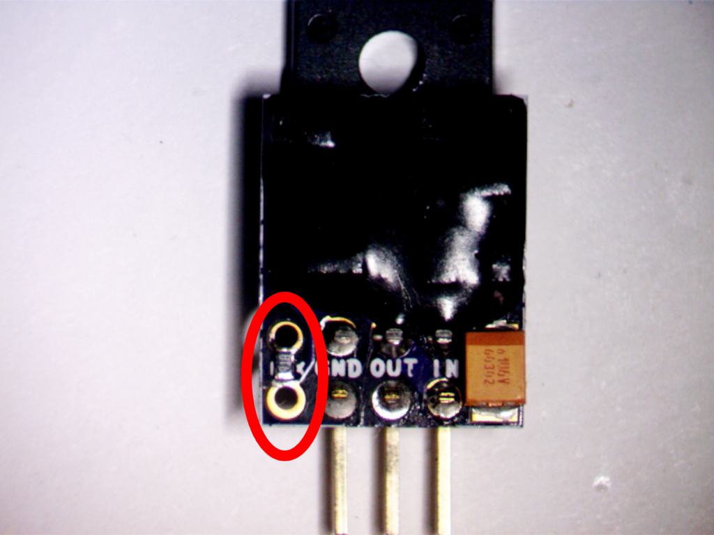
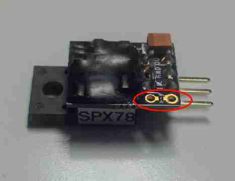
SPX17, SPX78 and SPX79 are available with variable output by adding a resistor here:
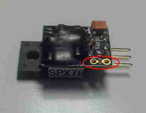
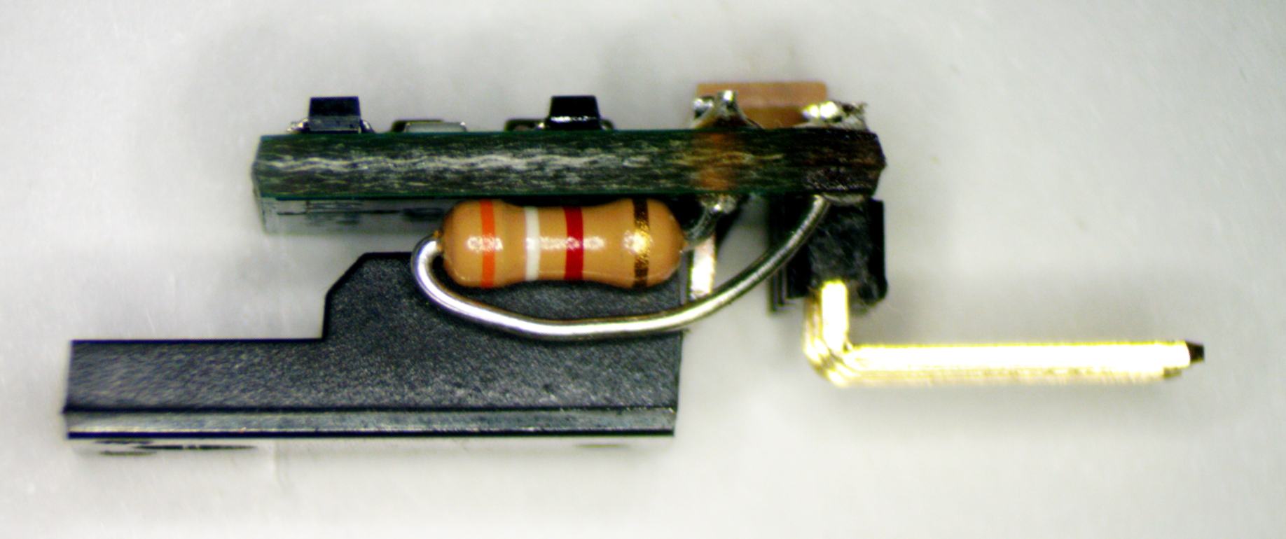
When shipped, variable SPX has Vout=30V, so add a resistor to set the correct voltage before you connect it and power it on!
The only difference between variable and fixed Vout is if we add the extra resistor or if you add it. We add a thin film 0603 SMD, you can add same or a ⅛W resistor of your technology choice. The additional Rset resistor is in parallel with a 10k resistor so Vout change is not linear with Rset change. You can also add a 4th pin and put a fixed resistor or potentiometer on the main PCB. See the chart below for values.
Calculate Rset in kΩ as
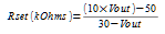
![]()
Typical values are
| Vout | Rset in Ω | Nearest 1% value (Ohms) |
Nominal Vout |
| 5 | 0 | 0 | 5 |
| 6.3 | 548.52 | 549 | 6.3 |
| 7 | 869.57 | 866 | 6.99 |
| 8 | 1363.64 | 1370 | 8.01 |
| 9 | 1904.76 | 1910 | 9.01 |
| 10 | 2500 | 2490 | 9.98 |
| 12 | 3888.89 | 3900 | 12.01 |
| 12.6 | 4367.82 | 4320 | 12.54 |
| 15 | 6666.67 | 6650 | 14.98 |
| 16 | 7857.14 | 7870 | 16.01 |
| 18 | 10833.33 | 10700 | 17.92 |
| 20 | 15000 | 15000 | 20 |
| 24 | 31666.67 | 31600 | 23.99 |
| 30 | none | none | 30 |
You can use a potentiometer to set Vout. A 50k trimmer will adjust from 25.8V to 5V, a 100k trimmer will adjust from 27.7V to 5V. The trimmer is in parallel with a 10k resistor so Vout change is not linear with resistance change.
How does SPX work better than other voltage regulators?
A unique circuit, granted US patent 8294440 in 2012, uses a JFET as a voltage level shifter, allowing a precision current source and feedback loop to be powered from the quiet, clean, low noise regulator output. The precision current is used to offset the floating regulator, allowing it to work at any output voltage. For more information, read this white paper, or the patent.
Download full data sheet (PDF)
| Parameter | Conditions | Value | Units |
|---|---|---|---|
| Input voltage maximum | 35 | V | |
| Output voltage positive | variable (4*) | +3.3 to +30 | V |
| Output voltage negative | variable | −5 to −30 | V |
| Output noise | RMS 20Hz – 20kHz (3*) | <1 | PPM of Vout |
| Line rejection | 60Hz, 1Vpp | 135 | dB |
| 80kHz, 1Vpp | 119 | ||
| Continuous current (within power dissipation limit) |
Positive (SPX78, SPX17) | 3 | A |
| Negative (SPX79) | −3 | ||
| Maximum power dissipation (2*) | no heat sink | 1 | W |
| sufficient heat sink | 36 | ||
| Drop-out voltage | Load current 0.5A | 0.6 | V |
| Load current 1A | 0.8 | ||
| Load current 2A | 1 | ||
| Load current 3A | 1.5 | ||
| Output impedance | 20Hz – 20kHz | 25 | mΩ |
NOTE! This calculator only applies to a linear transformer+rectifier+filter cap power source. It is not accurate if the raw source is a SMPS.
Use this calculator to select a suitable heat sink for your Superpower regulator. The Max Heat Sink value is the highest thermal resistance allowed for the given conditions. The bigger the thermal resistance, the smaller the heat sink.
Calculator fields have only minimum validation so if the Vrms result has something bizarre (like "NaN"), recheck your input values. If Vin is negative, Vout must also be negative, otherwise the calculations are incorrect.
Heat Sink
The value in the Max heat sink °C/W box shows the maximum thermal resistance for a heat sink on a Superpower with the given Vin. The heat sink calculation assumes a 75°C temperature increase of the regulator.
Assumptions
- Input voltage is DC or DC equivalent in Vrms
- Select SP for current < 500mA, SPJ or SPL for higher currents
- Calculator only works to 3A
- Heat sink allows 75°C temperature rise due to power dissipation
Can this calculator be used for any voltage regulator?
It can be used for any series voltage regulator if you know the drop-out voltage. For Superpower Type choose Custom regulator and enter the drop-out value for your regulator at the given load current.
Superpower Transformer Calculator
Use this calculator to decide the best transformer to use for your Superpower supply. Given the values you enter, it computes the ripple, decides the drop out voltage based on selected Superpower type and load current, sums everything and calculates the minimum Vrms of the transformer.
Calculator fields have only minimum validation so if the Vrms result has something bizarre (like "NaN"), recheck your input values. If Vrms is negative, Load current exceeds the capability of the selected Superpower type.
Heat Sink
The value in the Max heat sink °C/W box shows the maximum thermal resistance for a heat sink on a Superpower with the Vin shown in Regulator input Vpeak with the other values as given. To see the heat sink needed for a different Vin, change the value in Line Voltage Variation until the Regulator input Vpeak equals the Vin you will use in your application. The heat sink calculation assumes a 75°C temperature increase of the regulator.
Assumptions
- Linear power supply with transformer/rectifier/filter caps/Superpower
- Transformer has sufficient power that it does not sag under load (use safety margin to account for sag)
- Vdc of rectifier output is minimum value + safety margin
- Full wave center tapped rectifier follows the transformer.
For a bridge with no center tap, double the diode drop - Transformer output voltage is specified as Vrms
- Filter capacitance is entered in µF
- Select the power line frequency for your locale
- Regulator dissipation assumes nominal line voltage but allows for a drop of line variation % without losing regulation
- Rectifier diode drop allows entry of Si, SiC or other diode drop
- Heat sink allows 75°C temperature rise due to power dissipation
Special thanks to a customer whose suggestions helped us improve this calculator...you know who you are!
FAQ
How can Vrms be less than Vout?
Transformers are specified as Vrms. Full wave rectified and filtered transformer voltage is, with no load, approximately Vpeak, which is Vrms X sqrt(2). So Vrms is lower than the Vpeak required at the regulator's input, and with low output current requirements, may be lower than regulator Vout.
Why is Vrms negative and almost 1000?
The calculator does this when Load Current exceeds the capability of the selected Superpower type.
What kind of capacitors should I use for a rectifier filter?
Use the electrolytic capacitor of your choice. The most important issue for regulation is to have sufficient capacitance to prevent ripple that goes below Vout+Vdropout.
Should I bypass the filter capacitors with ceramic?
Yes, a 0.1µF ceramic cap at the Superpower Vin terminal helps reduce high frequency noise and RF. This amount or more capacitance should be placed at the Vin terminal to ground to prevent possible low level oscillation at some load current values. This does not affect the calculation very much.
How much filter capacitance should I use, can I use too much?
More filter capacitance is better, it reduces ripple. When the room lights start to dim as you switch on the power supply, you may be reaching the point of "too much." Or maybe you should run a separate mains wire for your audio system :-).
Can this calculator be used for any voltage regulator?
It can be used for any series voltage regulator if you know the drop-out voltage. For Superpower Type choose Custom regulator and enter the drop-out value for your regulator at the given load current.
Superpower regulator
Dissipation & heat sink calculator
Works out how much heat the regulator has to shed at your operating point, and the largest thermal resistance a heat sink may have to hold the rise near 75 °C. Figures assume a linear supply — transformer, rectifier and filter cap. A switching supply upstream makes them meaningless.
Operating point
Readout
Heat load
Max sink °C/W
The highest thermal resistance a heat sink may have here. Bigger number, smaller sink. Anything at or below the figure shown holds the rise to roughly 75 °C in free air.
What the maths does
Dissipation is (Vin − Vout) × (Iload + 10 mA), the extra 10 mA covering the regulator's own draw. Sink resistance is 75 °C divided by that wattage.
Drop-out
Vin − Vout must stay above the drop-out figure or the regulator stops regulating and passes ripple straight through. Choose Other series regulator to enter the drop-out from your own datasheet.
Superpower regulator
Transformer calculator
Sizes the transformer for a Superpower supply. It works out the ripple, picks the drop-out voltage from the regulator and load current, adds the headroom you allow for line sag and safety margin, and returns the minimum secondary Vrms along with the heat the regulator will have to shed.
Regulator
Supply
Readout
Heat load
Reading the heat sink figure
Max sink is the highest thermal resistance a sink may have at the Vpeak shown, holding the regulator's rise to roughly 75 °C. Bigger number, smaller sink. To see the sink for a different input voltage, adjust line variation until Vpeak matches the figure you plan to run.
Where the numbers come from
Ripple is Iload ÷ (C × 2f). Vpeak stacks output, ripple and drop-out, adds the safety margin, then divides by the line variation you allow. Vrms is Vpeak ÷ √2 plus the diode drop. Dissipation is taken at the ripple trough, and sink resistance is 75 °C divided by it.
Assumptions
- Linear supply: transformer, rectifier, filter caps, Superpower.
- The transformer is stiff enough that it does not sag under load. Use the safety margin to cover sag.
- Rectifier output Vdc is the minimum value plus the safety margin.
- Choosing a bridge doubles the diode drop you enter, since two diodes conduct in series.
- Transformer output is specified as Vrms; capacitance is entered in µF.
- Dissipation assumes nominal line voltage but tolerates a sag of the line variation percentage without losing regulation.
- The heat sink figure allows a 75 °C rise.
Questions
How can Vrms be less than Vout?
Transformers are specified in Vrms. Once rectified and filtered, the voltage sits near Vpeak, which is Vrms × √2. So the secondary Vrms is lower than the peak arriving at the regulator, and at low output currents it can even fall below the regulator's output voltage.
What kind of capacitors should I use for the filter?
Any electrolytic you like. What matters for regulation is enough capacitance that the ripple trough never dips below Vout plus the drop-out voltage.
Should I bypass the filter capacitors with ceramic?
Yes. A 0.1 µF ceramic at the Superpower Vin terminal cuts high frequency noise and RF. Put at least that much from Vin to ground to head off low level oscillation at some load currents. It barely affects the calculation.
How much filter capacitance, and can I use too much?
More is better, it reduces ripple. When the room lights dim as you switch the supply on, you may be approaching too much. Or perhaps the audio system wants its own mains run.
Can this be used with any voltage regulator?
Any series regulator, as long as you know its drop-out voltage. Choose Other series regulator and enter the drop-out from the datasheet at your load current.
With thanks to the customer whose suggestions improved this calculator. You know who you are.