




Why buy from us?
Lorem Ipsum is simply dummy text of the printing and typesetting industry.
Ask a Question About This Product
- Stock: In Stock
- Model: SPHP Positive
- Weight: 3.00g
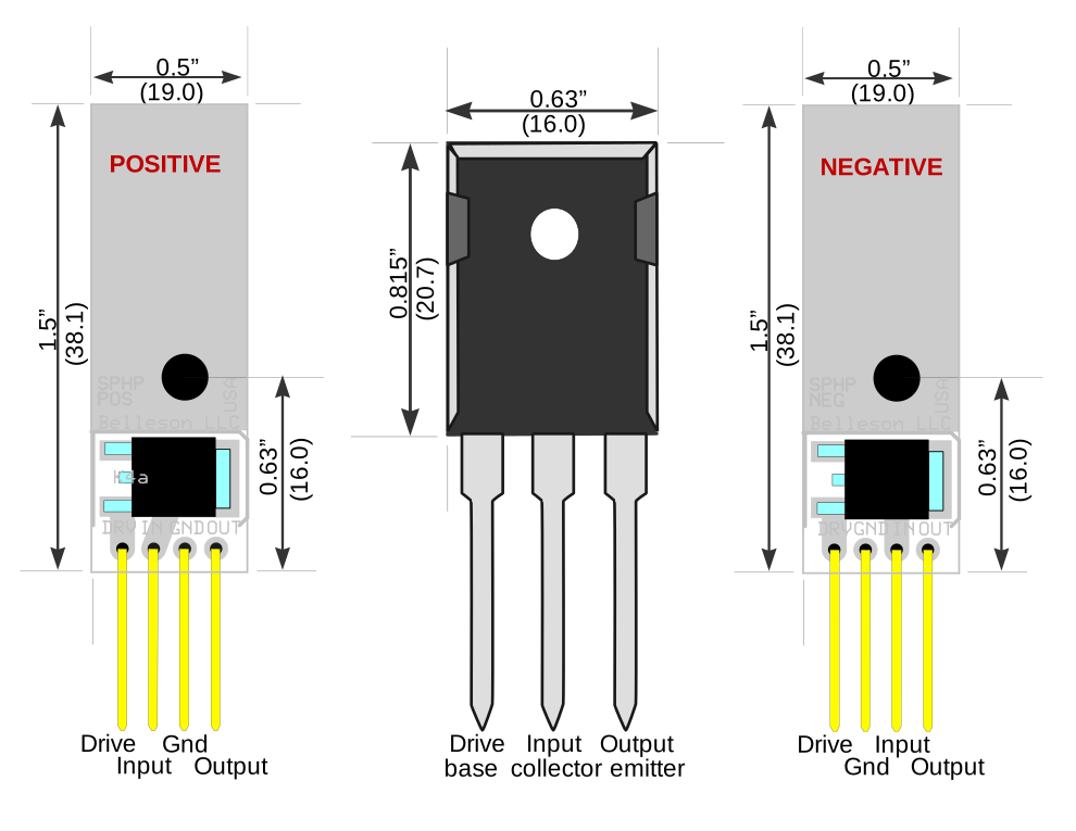
- Dimensions: 1.50in x 0.50in x 0.50in
- SKU: SPHPP
Belleson's SPHP Superpower can deliver up to 10A at 100V. This is enough for most power amplifiers and to replace noisy and slow switched mode power supplies in computer based music servers. High current circuit design requires careful thought about power dissipation, where current flows and other important topics. We'll discuss this diagram of a basic power supply using SPHP:  . To start, let's define some terms:
- VIN
- Input voltage to regulator
- VOUT
- Voltage regulator output
- VDO
- Regulator drop-out voltage: minimum (VIN-VOUT) to keep regulation
- IL
- Load current from regulator output to its load and back to power source (typically a transformer+rectifier+filter)
- PL
- Load dissipation: VOUT / IL
- PR
- Regulator dissipation: (VIN - VOUT) / IL
- LDO
- Low Drop Out
- VRIP
- Input Ripple, the AC change at VIN
Power Dissipation—Regulator vs. Load
SPHP can provide up to 1000W to a load while the regulator can dissipate 200W. Total load dissipation is thus 1200W. You must choose a power transformer with high enough VA to supply the total power.
Any power used by the regulator is not delivered to the load and is considered wasted. Given regulator power dissipation = drop-out voltage times load current, it's easy to see why low drop-out voltage is important, and why LDO is a standard acronym in regulator data sheets. The closer VIN is to VOUT, the less power is wasted.
Drop–Out Voltage and Supply Efficiency
SPHP drop-out, as for most linear regulators, increases with load current to a maximum of 3V at 10A. Thus it is theoretically possible to make a 1000 Watt power supply with 30W of wasted power, giving an efficiency of 97%. Practically speaking, however, an efficiency of 80% is considered great for a high power linear supply. Why is this?
Looking at the above schematic, AC current is rectified by bridge rectifier BR1 and filtered (smoothed) by capacitor C1. After mains power is applied, C1 charges to its peak DC value and will remain charged until current is requested by the load. Realize that C1 only charges when the peak voltage from BR1 goes above C1 voltage so for much of the AC cycle, C1 can supply current but not receive it.
Input Ripple Voltage and Regulation
While C1 is supplying current and bridge voltage is below C1 voltage, C1 discharges. There is a long time (relative to a power line cycle) when C1 discharges and a short time when it recharges. This is what makes the familiar saw tooth voltage ripple at the input to the regulator. 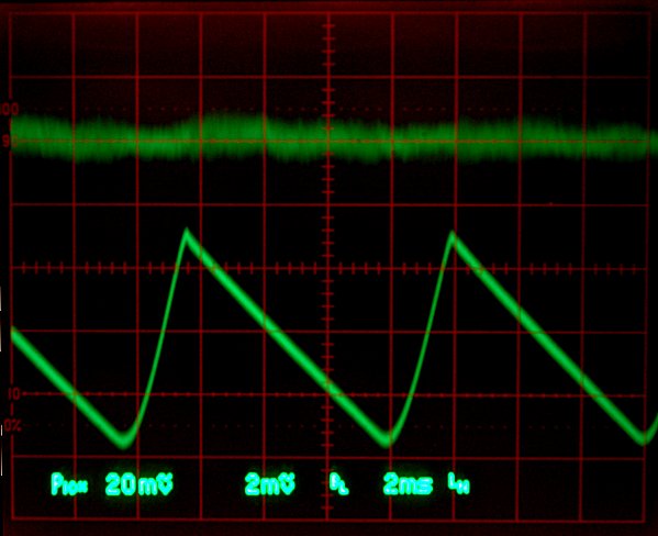
As you know, i=Cdv/dt and higher load current discharges C1 more quickly. If C1 discharges enough during an AC power line cycle to go below (VOUT+VDO), the regulator stops regulating!
Regulator Input Capacitance and Drop Out Voltage
Look again at i=Cdv/dt. Rearranging terms gives dv=idt/C to show that ripple is reduced by increasing C. Now rearrange again and substitute frequency f=1/dt to get an equation for C1 given load current and maximum desired ripple: C=i/(2fdv). The factor of 2 is because BR1 is a full wave rectifier and C charges twice per cycle. A half wave rectifier does not have this factor.
For 10A load and 1V maximum ripple at a 50Hz power line cycle (worst case, also makes the math prettier), and 1V maximum ripple target, the required C1=10/100, or 100000µF. The 47000µF value assigned to C1 in the above schematic will allow about 2.5V maximum ripple voltage.
Given that the minimum ripple voltage must stay above VOUT+VDO, the voltage at BR1 must go above VOUT+VDO+VRIP to keep C1 charged enough to allow the regulator to function correctly. For a 12V regulator, BR1 voltage must stay above 12+3+2.5=17.5V using C1=47000µF. This explains why a supply efficiency of 97% is unrealistic. For this 12V regulator, efficiency is 100 x 12 / 17.5 = 69%. Even with C1=100000µF, efficiency goes to 75% which wastes 1/4 of the input power. Ripple depends only on load current, so given the same load and VDO, a higher VOUT supply will be more efficient than a lower VOUT supply.
Here is a really good tutorial on building a 10A power supply
General Conclusions
- Power dissipation by the regulator is linear as (Vin-Vout)*(load current)
- (Vin - Vout) is RMS voltage
- If Vin is fed from a rectifier+filter cap, Vin is not DC but has ripple
- Ripple has a linear dependence on load current as
dv=i/(2fC)
where dv = ripple amplitude, i=RMS load current, f = power line frequency and C=filter capacitance - Minimum peak of ripple must not go below (Vout + Vdropout), otherwise regulator stops regulating
From this we conclude:
- Larger filter capacitance = lower ripple
- Lower ripple allows lower Vin
- Lower Vin allows lower regulator power dissipation
More Overhead
For the chosen 12V supply, the transformer must keep VIN above 17.5V to maintain regulation. With high current demand, transformer secondary voltage tends to sag (decrease). The peak unloaded voltage of the transformer must be increased to account for sag, and also to account for the worst case low primary voltage. Ultimately this transformer must have a 20V to 24V peak output voltage due to these multiple system constraints.
High Current and Physical Design
Now that we've decided on a set of components: SPHP regulator, power transformer, bridge rectifier, large filter capacitor, how do we connect them? Two important factors in wiring an accurate high current power supply are wiring resistance and stability. At 10A, 10mΩ equates to a 0.1V drop. As current changes through an impedance, it will modulate the voltage at the load, so even with a perfect voltage source, a changing high current load can modulate the voltage at the load due to wiring resistance.
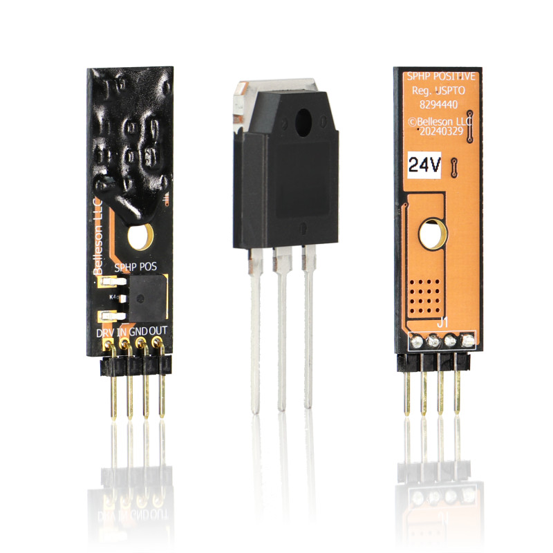
SPHP is designed with a small PCB controller and a separate high current output transistor (QN1 in the schematic). This allows the control loop to be independently placed and wired with a maximum current of about 250mA, and QN1 can be separately heat sink mounted with large currents flowing separately through it.
The diagram below shows physical wiring of the above schematic with matching wire colors. Notice the red path of high current from the raw supply to the power transistor to the load and back to the raw supply. Make this path short, from heavy gauge copper trace or wire. The black and green DRV current paths can be smaller, they will have approximately 250mA at full 10A regulator current. The other paths are very low current.
 .
.
Two external protection diodes allow stored charge from large capacitance to by-pass the regulator at power-down if input voltage falls faster than output voltage or if VOUT gets pulled below ground by some load related condition (e.g. an inductive load). Even though SPHP has internal protection diodes, larger external ones such as 1N4004 are recommended.
SPHP has no built-in stabilizing capacitor, so an external one must be connected from VOUT to ground as shown here. This should be 100µF or more and have a voltage rating higher than VOUT. Also notice the diagram is not to scale—the capacitor will be bigger than the Superpower :-).
The power transistor supplied with SPHP is NJW3281G, a 250V, 15A, 200W device.
Preventing Damage
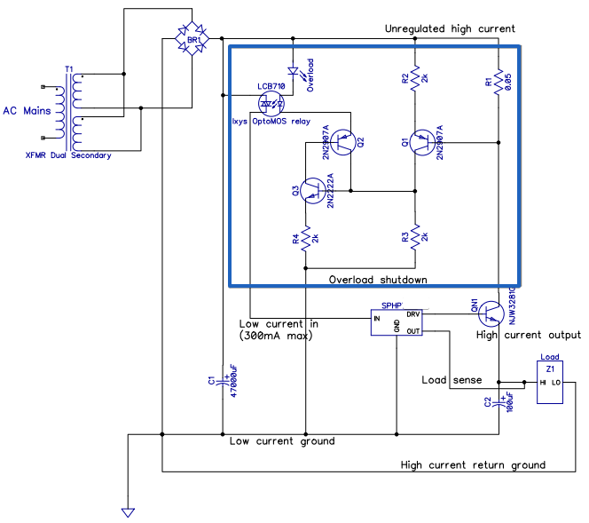
With 10A+ available, it's easy to damage a regulator with even the briefest of short circuit to ground. The fast shutdown circuit shown below can prevent this:
 .
.
It's a latching protection circuit that shuts off the internal control loop and prevents any output current from the regulator. To reset, VIN must be powered down and up again.
Good Luck!
Hopefully this is sufficient information to build the power supply of your dreams! Contact us with any further questions and we'll help.
ATTENTION! SPHP users please read this.
As you know, SPHP is a high power voltage regulator. To quote Spiderman's Uncle Ben (who was quoting Sir Winston Churchill), “With great power comes great responsibility.” Please note the following and be careful during design and testing of your power supply:

-
Use extreme caution with high voltage circuits, this circuit can deliver lethal voltage and current. Keep one hand in your pocket!
-
There is no internal limit on output current. With 10+ amps, SPHP is unforgiving of mistakes and is quickly destroyed by an output short circuit or other incidents. If possible, use an inexpensive monolithic substitute such as LT1084 for new designs, then replace with SPHP when design is fully functional. The IN/GND/OUT pins on positive SPHP controller and GND/IN/OUT on negative SPHP match LM78xx and LM79xx pin connections for temporary substitution at lower voltage and current.
-
Output voltage is factory adjusted to 12V during testing. If your system is designed for high voltage Vout and thus has high input voltage, adjust SPHP to the desired output voltage under NO LOAD. In other words, if you power up SPHP under load with 12V output but Vin = 80V (for example) and load current = 5A, that puts the regulator output transistor under 340W load until Vout is adjusted to its correct value. This will destroy the output transistor and probably the regulator controller.
-
Vout adjustment is reverse of convention— clockwise decreases Vout, counter-clockwise increases Vout.
-
For best transient response, place a 100Ω resistor between base and emitter of the output power transistor.
-
For best stability across all load current, place a 0.1µF polypropylene capacitor from Vin to GND pins near the regulator control PCB.
-
SPHP has two internal protection diodes, however they are small SMD devices. If your application has large capacitance at regulator input and output, two external high current protection diodes (e.g. 1N4007) from [Vout to Vin] and [GND to Vout], [given anode to cathode], will improve long term reliability.
-
The Superpower data sheet has a special section discussing SPHP. Also read the tab FAQ:10A Power Supply before requesting support.
Belleson's SPHP Superpower can deliver up to 10A at 100V. This is enough for most power amplifiers and to replace noisy and slow switched mode power supplies in computer based music servers. High current circuit design requires careful thought about power dissipation, where current flows and other important topics. We'll discuss this diagram of a basic power supply using SPHP: . To start, let's define some terms:
- VIN
- Input voltage to regulator
- VOUT
- Voltage regulator output
- VDO
- Regulator drop-out voltage: minimum (VIN-VOUT) to keep regulation
- IL
- Load current from regulator output to its load and back to power source (typically a transformer+rectifier+filter)
- PL
- Load dissipation: VOUT / IL
- PR
- Regulator dissipation: (VIN - VOUT) / IL
- LDO
- Low Drop Out
- VRIP
- Input Ripple, the AC change at VIN
Power Dissipation—Regulator vs. Load
SPHP can provide up to 1000W to a load while the regulator can dissipate 200W. Total load dissipation is thus 1200W. You must choose a power transformer with high enough VA to supply the total power.
Any power used by the regulator is not delivered to the load and is considered wasted. Given regulator power dissipation = drop-out voltage times load current, it's easy to see why low drop-out voltage is important, and why LDO is a standard acronym in regulator data sheets. The closer VIN is to VOUT, the less power is wasted.
Drop–Out Voltage and Supply Efficiency
SPHP drop-out, as for most linear regulators, increases with load current to a maximum of 3V at 10A. Thus it is theoretically possible to make a 1000 Watt power supply with 30W of wasted power, giving an efficiency of 97%. Practically speaking, however, an efficiency of 80% is considered great for a high power linear supply. Why is this?
Looking at the above schematic, AC current is rectified by bridge rectifier BR1 and filtered (smoothed) by capacitor C1. After mains power is applied, C1 charges to its peak DC value and will remain charged until current is requested by the load. Realize that C1 only charges when the peak voltage from BR1 goes above C1 voltage so for much of the AC cycle, C1 can supply current but not receive it.
Input Ripple Voltage and Regulation
While C1 is supplying current and bridge voltage is below C1 voltage, C1 discharges. There is a long time (relative to a power line cycle) when C1 discharges and a short time when it recharges. This is what makes the familiar saw tooth voltage ripple at the input to the regulator.
As you know, i=Cdv/dt and higher load current discharges C1 more quickly. If C1 discharges enough during an AC power line cycle to go below (VOUT+VDO), the regulator stops regulating!
Regulator Input Capacitance and Drop Out Voltage
Look again at i=Cdv/dt. Rearranging terms gives dv=idt/C to show that ripple is reduced by increasing C. Now rearrange again and substitute frequency f=1/dt to get an equation for C1 given load current and maximum desired ripple: C=i/(2fdv). The factor of 2 is because BR1 is a full wave rectifier and C charges twice per cycle. A half wave rectifier does not have this factor.
For 10A load and 1V maximum ripple at a 50Hz power line cycle (worst case, also makes the math prettier), and 1V maximum ripple target, the required C1=10/100, or 100000µF. The 47000µF value assigned to C1 in the above schematic will allow about 2.5V maximum ripple voltage.
Given that the minimum ripple voltage must stay above VOUT+VDO, the voltage at BR1 must go above VOUT+VDO+VRIP to keep C1 charged enough to allow the regulator to function correctly. For a 12V regulator, BR1 voltage must stay above 12+3+2.5=17.5V using C1=47000µF. This explains why a supply efficiency of 97% is unrealistic. For this 12V regulator, efficiency is 100 x 12 / 17.5 = 69%. Even with C1=100000µF, efficiency goes to 75% which wastes 1/4 of the input power. Ripple depends only on load current, so given the same load and VDO, a higher VOUT supply will be more efficient than a lower VOUT supply.
Here is a really good tutorial on building a 10A power supply
General Conclusions
- Power dissipation by the regulator is linear as (Vin-Vout)*(load current)
- (Vin - Vout) is RMS voltage
- If Vin is fed from a rectifier+filter cap, Vin is not DC but has ripple
- Ripple has a linear dependence on load current as
dv=i/(2fC)
where dv = ripple amplitude, i=RMS load current, f = power line frequency and C=filter capacitance - Minimum peak of ripple must not go below (Vout + Vdropout), otherwise regulator stops regulating
From this we conclude:
- Larger filter capacitance = lower ripple
- Lower ripple allows lower Vin
- Lower Vin allows lower regulator power dissipation
More Overhead
For the chosen 12V supply, the transformer must keep VIN above 17.5V to maintain regulation. With high current demand, transformer secondary voltage tends to sag (decrease). The peak unloaded voltage of the transformer must be increased to account for sag, and also to account for the worst case low primary voltage. Ultimately this transformer must have a 20V to 24V peak output voltage due to these multiple system constraints.
High Current and Physical Design
Now that we've decided on a set of components: SPHP regulator, power transformer, bridge rectifier, large filter capacitor, how do we connect them? Two important factors in wiring an accurate high current power supply are wiring resistance and stability. At 10A, 10mΩ equates to a 0.1V drop. As current changes through an impedance, it will modulate the voltage at the load, so even with a perfect voltage source, a changing high current load can modulate the voltage at the load due to wiring resistance.
SPHP is designed with a small PCB controller and a separate high current output transistor (QN1 in the schematic). This allows the control loop to be independently placed and wired with a maximum current of about 250mA, and QN1 can be separately heat sink mounted with large currents flowing separately through it.
The diagram below shows physical wiring of the above schematic with matching wire colors. Notice the red path of high current from the raw supply to the power transistor to the load and back to the raw supply. Make this path short, from heavy gauge copper trace or wire. The black and green DRV current paths can be smaller, they will have approximately 250mA at full 10A regulator current. The other paths are very low current.
.
Two external protection diodes allow stored charge from large capacitance to by-pass the regulator at power-down if input voltage falls faster than output voltage or if VOUT gets pulled below ground by some load related condition (e.g. an inductive load). Even though SPHP has internal protection diodes, larger external ones such as 1N4004 are recommended.
SPHP has no built-in stabilizing capacitor, so an external one must be connected from VOUT to ground as shown here. This should be 100µF or more and have a voltage rating higher than VOUT. Also notice the diagram is not to scale—the capacitor will be bigger than the Superpower :-).
The power transistor supplied with SPHP is NJW3281G, a 250V, 15A, 200W device.
Preventing Damage
With 10A+ available, it's easy to damage a regulator with even the briefest of short circuit to ground. The fast shutdown circuit shown below can prevent this:
.
It's a latching protection circuit that shuts off the internal control loop and prevents any output current from the regulator. To reset, VIN must be powered down and up again.
Good Luck!
Hopefully this is sufficient information to build the power supply of your dreams! Contact us with any further questions and we'll help.